
![[Top]](../../images/home.jpg)
![[Contents]](../../images/contents.jpg)
![[Prev]](../../images/previous.jpg)
![[Next]](../../images/next.jpg)
![[Last]](../../images/index.jpg)


Getting Acquainted with the MAX
This chapter covers these topics:
Using the MAX as an ISP or telecommuting hub
The MAX is a high-performance WAN router that can be used to concentrate many incoming switched connections to a corporate backbone or to another network, such as the Internet or a Frame Relay network.
A switched connection is a temporary link between devices, established only for the duration of a call. When you use bandwidth-on-demand, the MAX adds and subtracts bandwidth as necessary, keeping connection costs as low as possible. Of course, the MAX also supports leased connections for those users whose connection times justify a permanent virtual connection to the backbone network.
The most common uses of the MAX are as an ISP (Internet Service Provider) hub, to manage many switched IP connections to the Internet, and as a telecommuting hub, to provide high-speed connections between a corporate backbone and remote locations. Its configuration options provide the flexibility you need to optimize your installation. Management features include a comprehensive set of control and monitoring functions and easy upgrades.
Note: If you have a MAX running Multiband Simulation, bridging and routing are disabled.
Also, the following terminal server commands do not apply: close, ipxping, open, resume,
rlogin, telnet.
Using the MAX as an ISP hub
Individuals subscribe to an Internet Service Provider to get a TCP/IP connection to the Internet. Subscribers dial in to a local Point-of-Presence (POP), typically using an analog modem, an ISDN V.120 terminal adapter (such as a BitSurfer), or an ISDN router such as an Ascend Pipeline. When used as an ISP hub, the MAX is configured as an IP router that establishes the dial-in WAN connection with subscribers and routes their data stream to other Internet routers.
Figure 1-1 shows a typical ISP configuration with three POPs. Each POP has at least one MAX on an Ethernet, with another Internet router (such as a Cisco router) on that LAN.
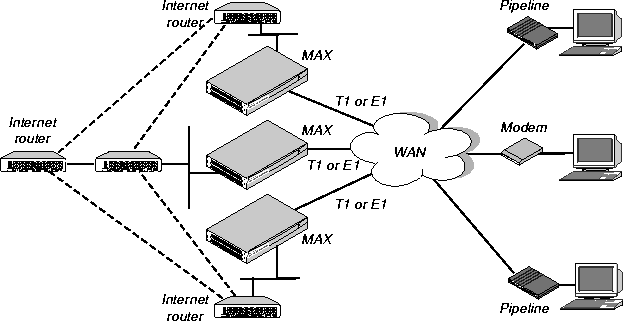
Figure 1-1. Using the MAX as an ISP hub
Typically, the MAX has T1 or E1 lines using ISDN signaling to connect to the WAN and handle the incoming switched connections. To connect to Internet routers, the MAX most often uses the local Ethernet, but it could also use serial WAN, nailed T1, nailed E1, or Frame Relay.
The connections between Internet routers can be any high bandwidth connection, such as Frame Relay, nailed T1, nailed E1, HSSI, FDDI, or Sonet. Large ISPs often support redundant MAX units and Internet routers on each Ethernet segment.
Using the MAX as a telecommuting hub
Telecommuters are typically users at branch offices, at home, at customer sites, at vendor sites, and on the road. The MAX enables these remote users to access the corporate backbone just as though they were connected locally. The backbone may be a NetWare LAN, an IP network, or a multi-protocol network. Figure 1-2 shows an example where home users, remote offices, and customer sites access the backbone network.
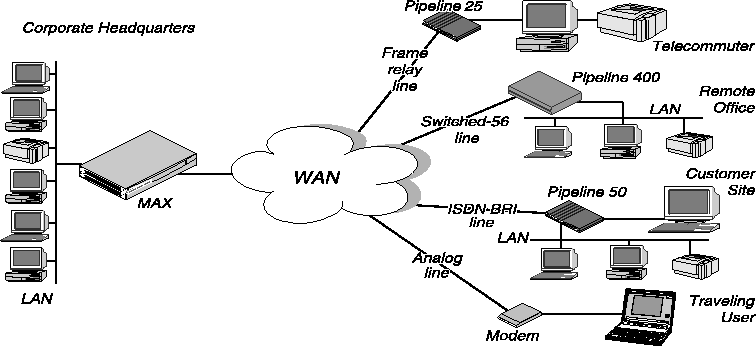
Figure 1-2. Using the MAX as a telecommuting hub
In this example network, a telecommuter in a home office logs into the corporate LAN using a Pipeline 25 and Frame Relay. Users on a remote office LAN access the backbone via a Pipeline 400 with a switched-56 connection. A customer can access selected corporate network resources using a Pipeline 50 with an ISDN BRI connection. A mobile user with an analog modem can dial into the backbone, provided that the MAX has a digital modem card installed.
Notice that each user can access the MAX through a different type of line. One user may access the MAX by using the switched services on an ISDN BRI or Switched-56 line, while another user might require a nailed 56K Frame Relay circuit.
Overview of MAX configuration
This section provides an overview of configuring the MAX. This section contains:
- Configuring the lines, channels, and ports, and how calls are routed between them
- Configuring wide area network connections and security
- Configuring the MAX as a Frame Relay or X.25 concentrator
- Configuring routing and bridging across the WAN
- Configuring Internet services, such as multicast, OSPF, and virtual private networks
Creating a network diagram
Ascend strongly recommends that, after you have read this introductory material, you diagram your network and refer to the diagram while configuring the MAX. Creating a comprehensive network diagram helps prevent problems during installation and configuration, and can help you troubleshoot problems later.
Configuring lines, slots, and ports for WAN access
The MAX has four built-in T1 or E1 lines and a V.35 serial port (8 Mbps). Each T1 and E1 line has a wide variety of configuration options, including whether or not ISDN signaling is used, type of physical-layer framing, cable length, and telco options. The way you configure each line affects how much bandwidth will be available and whether you can direct outbound calls to use specific channels. The way you configure channels depends on your connectivity needs.
The serial WAN port is typically used for a leased high-speed connection to a Frame Relay switch or to another WAN router. The port itself requires little configuration. Most of the required information is specified in a Frame Relay or Connection profile.
You can add expansion modules to support additional bandwidth (BRI lines), serial host ports modules to support videoconferencing, and digital modems to support analog modem connections over digital lines. The lines and ports on the modules (cards) have their own configuration requirements, including the assignment of phone numbers and information about routing calls.
Once you have enabled the lines, slots, and ports for WAN access, you need to configure the manner in which calls will be routed to them (for dial-out access to the WAN) and routed from them to other destinations (such as the local network).
Configuring WAN connections and security
When the MAX receives packets that require establishment of a particular WAN connection, it automatically dials the connection. Software at both ends of the connection encapsulates each packet before sending it out over the phone lines. Each type of encapsulation supports its own set of options, which can be configured on a per-connection basis to enable the MAX to interact with a wide range of software and devices.
After a connection's link encapsulation method has been negotiated, the MAX typically uses a password to authenticate the call. Authentication and authorization are both described fully in the MAX Security Supplement. Following are some of the connection security features supported in the MAX:
Concentrating Frame Relay connections
The MAX provides extensive support for Frame Relay. Using a T1 or E1 line or serial WAN port for a nailed connection to a switch, it can function as an NNI (network-to-network interface) switch, a DCE (data communications equipment) unit responding to users, or as a DTE (data terminal equipment) requesting services from a switch.
Enabling X.25 terminal connections
X.25 is a precursor to Frame Relay and is generally considered less efficient. However, many sites use it to transmit information between users across the WAN. It accommodates both high-volume data transfers and interactive use of host machines. The MAX may have one physical connection to an X.25 DCE using a T1, E1, or BRI line. To support interactive use, the connection must be nailed.
Configuring routing and bridging across the WAN
Routing and bridging configurations enable the MAX to forward packets between the local network and the WAN and also between WAN connections.
Enabling protocol-independent packet bridging
The MAX can operate as a link-level bridge, forwarding packets from Ethernet to a WAN connection (and vice versa) on the basis of the destination hardware address in each packet. Unlike a router, a bridge does not examine packets at the network layer. It simply forwards packets to another network segment if the address does not reside on the local segment.
Using IPX routing (NetWare 3.11 or newer)
The MAX can operate as an IPX router, linking remote NetWare LANs with the local NetWare LAN on Ethernet. IPX routing has its own set of concerns related to the client-server model and user logins. For example, users should remain logged in for some period even if the connection has been brought down to save connection costs.
IP routing
IP routing is the most widespread use of the MAX, and it has a wide variety of configurable options. IP routing is the required basis for Internet-related services such as IP multicast support, OSPF, and cross-Internet tunneling for virtual private networks. Most sites create static IP routes to enable the MAX to reliably bring up a connection to certain destinations or to change global metrics or preferences settings.
Configuring Internet services
All Internet services and routing methods require that the MAX function as an IP router, so an IP routing configuration is a necessary precondition.
Multicast
The multicast backbone (MBONE) is a virtual network layered on top of the Internet to support IP multicast routing across point-to-point links. It is often used for transmitting audio and video on the Internet in real-time because multicasting is a much cheaper and faster way to communicate the same information to multiple hosts.
OSPF routing
OSPF (Open Shortest Path First) is the next generation Internet routing protocol. The MAX can be configured to communicate with other OSPF routers within an autonomous system (AS). To enable this routing function, you must configure the OSPF options on the Ethernet interface and for each WAN connection that supports remote OSPF routers.
OSPF can import routes from RIP as well. You can control how these imported external routes are handled by adjusting systemwide routing options such as route preferences and ASE type metrics.
Virtual private networks
Many sites use the Internet to connect corporate sites or to enable mobile nodes to log into a corporate backbone. Such virtual private networks use cross-Internet tunneling to maintain security or to enable the Internet to transport protocols that it would otherwise drop, such as IPX. To implement virtual private networks, the MAX supports both ATMP, an Ascend-proprietary tunneling mechanism, and PPTP (Point-to-Point Tunneling Protocol).
ATMP enables the MAX to create and tear down a tunnel to another Ascend unit. In effect, the tunnel collapses the Internet cloud and provides what looks like direct access to a home network. Packets received through the tunnel must be routed, so ATMP applies only to IP or IPX networks at this time.
A PPTP session occurs between the MAX and a Windows NT server over a special TCP control channel. Either end may initiate a PPTP session and open the TCP control channel. Note that opening a PPTP session does not mean that a call is active, it simply means that a call can now be placed and received.
Overview of management features
This section describes management functions that use features built into the MAX. This section contains:
- Using the terminal server command line
- Using status windows to track WAN or Ethernet activity
- Managing the MAX using SNMP
- Using remote management to configure far-end Ascend units
- Updating software in the MAX unit's flash RAM
- Using Call Detail Reporting
The MAX provides up to nine security levels to control which management and configuration functions are accessible to users. These security profiles are described in detail in the MAX Security Supplement.
Using the terminal server command line
To invoke the terminal server command-line interface, you must have administrative privileges. Once you have activated a Security profile that enables these privileges, you can invoke the command line by selecting Term Serv in the Sys Diag menu. To close the command-line, use the Quit command at the command-line prompt. The command-line interface closes and the cursor returns to the vt100 menus.
Using status windows to track WAN or Ethernet activity
Eight status windows display on the right side of the screen in the MAX configuration menus. The windows provide a great deal of read-only information about what is currently happening in the MAX. If you want to focus on the activity of a particular slot card, you can change the default contents of the windows to show what is currently occurring in that slot.
Managing the MAX using SNMP
Many sites use Simple Network Management Protocol (SNMP) applications to obtain information about the MAX and make use of it to enhance security, set alarms for certain conditions, and perform simple configuration tasks.
The MAX supports the Ascend Enterprise MIB, MIB II, and some ancillary SNMP features. The MAX can send management information to an SNMP manager without being polled. SNMP security uses a community name sent with each request. The MAX supports two community names, one with read-only access, and the other with read/write access to the MIB.
Using remote management to configure far-end Ascend units
When you have an MP+ or AIM connection to another Ascend unit, you can use the management subchannel established by those protocols to control, configure, and obtain statistical and diagnostic information about that Ascend unit. Multi-level password security ensures that unauthorized personnel do not have access to remote management functions.
Flash RAM and software updates
Flash RAM technology enables you to perform software upgrades in the field without opening the unit or changing memory chips. You can upgrade the MAX through its serial port by accessing it either locally or through a dial-in modem. You cannot perform remote software upgrades over the WAN interface because of a conflict between running the WAN and reprogramming the software.
Call Detail Reporting (CDR)
Call Detail Reporting (CDR) is a feature that provides a database of information about each call, including date, time, duration, called number, calling number, call direction, service type, associated inverse multiplexing session, and port. Because the network carrier bills for bandwidth on an as-used basis, and bills each connection in an inverse multiplexed call separately, you may want to use CDR to understand and manage bandwidth usage and the cost of each inverse multiplexed session.
You can arrange the information to create a wide variety of reports which can be based on individual call costs, inverse multiplexed WAN session costs, costs on an application-by-application basis, bandwidth usage patterns over specified time periods, and so on. With the resulting better understanding of your bandwidth usage patterns, you can make any necessary adjustments to the ratio of switched to nailed bandwidth between network sites.
Where to go next
When you have planned your network, you are ready to configure the MAX. The flexibility of the MAX and its ever-increasing number of configurations means there is no set order for configuration. You can perform configuration tasks in any order you want. Table 1-1 shows you where to look for the information you need.
Table 1-1. Where to go next
To do this:
|
Go to this chapter or document:
|
|---|
|
Configure slots, lines, and ports
|
Chapter 2, Configuring the MAX for WAN Access.
|
|
Configure WAN connections
|
Chapter 3, Configuring WAN Links.
|
|
Set up Frame Relay
|
Chapter 4, Configuring Frame Relay.
|
|
Set up X.25
|
Chapter 6, Configuring X.25.
|
|
Set up packet bridging
|
Chapter 8, Configuring Packet Bridging.
|
|
Set up IPX routing
|
Chapter 9, Configuring IPX Routing.
|
|
Set up IP routing
|
Chapter 10, Configuring IP Routing.
|
|
Set up OSPF routing
|
Chapter 11, Configuring OSPF Routing.
|
|
Set up multicast forwarding
|
Chapter 12, Setting Up IP Multicast Forwarding.
|
|
Set up virtual private networks
|
Chapter 13, Setting Up Virtual Private Networks.
|
|
Set up SNMP access and traps
|
Chapter 14, MAX System Administration.
|
|
Manage the system
|
Chapter 14, MAX System Administration.
|
|
Work with status windows
|
MAX Reference Guide
|
|
Write configuration scripts
|
MAX MIF Supplement
|
|
Set up security
|
MAX Security Supplement
|
|
Set up RADIUS
|
MAX RADIUS Configuration Guide
|
techpubs@eng.ascend.com
Copyright © 1998, Ascend Communications, Inc. All rights
reserved.